


Symbols Electrical Powerpoint Ppt Template Bundles





Try Before you Buy Download Free Sample Product
 Impress Your
 Audience
 100%
100% Editable
 Save Hours
 of Time


Our Symbols Electrical Powerpoint Ppt Template Bundles are topically designed to provide an attractive backdrop to any subject. Use them to look like a presentation pro.
People who downloaded this PowerPoint presentation also viewed the following :
Symbols Electrical Powerpoint Ppt Template Bundles with all 17 slides:
Use our Symbols Electrical Powerpoint Ppt Template Bundles to effectively help you save your valuable time. They are readymade to fit into any presentation structure.










FAQs for Symbols Electrical Powerpoint
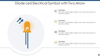
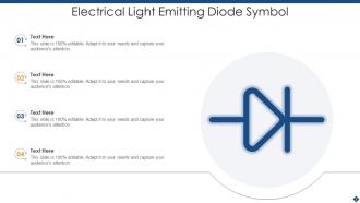
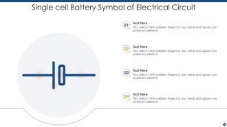
Yeah so the big ones you'll see constantly are resistors (that zigzag line), capacitors (two parallel lines), and batteries (long/short parallel lines). Ground symbols look like three horizontal lines stacked. Basic switches are just breaks in the line, LEDs are triangles with little arrows coming out. Diodes are triangles with a straight line next to them. Once you get these down, circuits aren't nearly as intimidating - probably like 90% of what you'll encounter uses these symbols. I used to keep a cheat sheet taped to my desk until I memorized them, which honestly didn't take that long.
Yeah, symbols totally change depending on what you're working with. Power guys use completely different ones for transformers than electronics people do - even basic stuff like resistors look different on power diagrams versus circuit schematics. Industrial automation has its own thing going on, especially with PLCs and motors. Telecom is basically a whole different language with fiber optics and all that. I learned this the hard way once, honestly. Always check the legend or standards doc first because assuming they're universal will mess you up. Each field pretty much does its own thing.
Look, standardization matters because you don't want some electrician halfway across the country wiring your design completely wrong. Everyone needs to read diagrams the same way or you get fires, electrocutions, all that bad stuff. IEEE and IEC standards basically create a universal language that works everywhere - honestly saves so much headache down the road. Your design process goes faster, troubleshooting becomes way less painful, and you stay compliant with safety rules. Quick tip: always double-check you're using the right symbols for your area when making schematics.
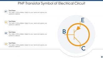
So basically, look for arrows and triangular shapes - those are your active components like transistors and op-amps that actually amplify stuff. Passive components are way simpler looking. Just rectangles, lines, and basic curves for resistors, capacitors, inductors. Honestly, once you notice the arrow pattern, you can't unsee it. Active = arrows pointing somewhere because they're doing something to the signal. Passive = boring geometric shapes because they're just sitting there storing energy or whatever. Makes reading schematics way faster when you can spot which ones need power vs which ones don't.
Start with the basic ones - resistors are those zigzag lines, capacitors look like parallel lines, transistors have arrows. It's kinda like learning a new language honestly, but way easier than it seems at first. The connecting lines between symbols? Those show you where current flows. I'd focus on memorizing maybe 10-15 common symbols before diving into anything fancy. Once you get the hang of reading a few simple circuits, the rest just clicks. Trust me, after a couple weeks you'll be looking at schematics like "oh yeah, that's obvious."
Honestly the biggest change was going from hand-drawn stuff to digital CAD in the 80s-90s. Those old hand-drawn schematics from the 60s actually look pretty sick though - way more personality than today's sterile computer symbols. Standards bodies like IEEE cleaned everything up, which was probably necessary but kinda boring. Resistors went from zigzag to boring rectangles internationally. We've got tons of new symbols now for PLCs, fiber optics, all the smart device stuff. Oh and if you're dealing with old equipment, grab a vintage symbol guide - you'll need it since the conventions were totally different back then.
Think of symbols as your troubleshooting GPS - they help you identify components fast and trace where signals should go. Without them, you're just staring at a mess of wires trying to guess what's wrong. I always start with the basic symbols first, then work through each section methodically. You can test components and compare your readings against what the symbol says should happen. Way easier than randomly poking around with a multimeter. Once you know the symbols, following current flow becomes pretty straightforward and you'll spot problems much quicker.
Dude, electrical symbols are literally your lifeline when designing equipment. They're like a universal language so nobody accidentally grabs a live wire (been there, not fun). Anyone looking at your circuit can instantly spot voltage levels, dangerous components, and what safety gear they need. Road signs for electricity, basically. You'll find protection devices and grounding points way faster too. Just make sure you're using current IEC or IEEE standards - old symbols actually make things more confusing. Trust me on that one.
AutoCAD Electrical and EPLAN are solid choices for this, or KiCad if you want something free. Most of these programs let you modify existing symbols or build new ones from scratch with basic shapes. Honestly, I'd just find something close to what you need first and tweak it - way faster than starting over. Your custom stuff should match standard line weights and proportions so it doesn't look weird next to normal symbols. Once you're done, save everything to your personal library. Oh, and don't forget clear labels for what each symbol actually does.
Really depends what you're doing tbh. KiCad's probably your best bet - it's free but actually good, which is rare. AutoCAD Electrical and Altium are the fancy professional ones if you've got the budget. I still mess around with Tinkercad when I need to sketch something quick (yeah I know it's basic but whatever). Fritzing's decent for beginners too. Oh and if you want simulation stuff, LTspice is solid. The symbol libraries are way better than they used to be across the board. Start with KiCad unless you just want something dead simple to learn on.
For electrical symbols, just use standard industry terms - don't get creative with naming. Put labels right next to the symbols, not scattered around like confetti. Arial or Calibri work fine, but make the text big enough so people can actually read it. Oh, and group similar symbols together because it looks way cleaner. If you're mixing symbol standards (which honestly gets confusing), throw in a legend. Skip the abbreviations unless they're super obvious. The whole thing should flow logically - I've sat through presentations where I spent half the time just trying to figure out what symbol was what.
Think of electrical symbols like learning to read music - once you know them, circuit diagrams make total sense instead of looking like hieroglyphics. You can sketch ideas super quickly rather than writing out "connect the battery's positive terminal to blah blah blah" every time. Start with the basics: resistors, batteries, switches. Then add capacitors and transistors. Honestly, troubleshooting gets so much easier when you're not squinting at a mess of words trying to figure out what connects where. It's basically the difference between having a map and wandering around lost. Trust me, memorizing these saves tons of time.
IEEE Standard 315 is what you want - that's the main one everyone uses. IEC 60617 works too if you're doing international stuff. But honestly? I just bookmark online databases like NEMA's site or even Wikipedia's electrical symbols page because digging through actual standards documents is a pain. Most CAD programs have the symbol libraries built right in anyway, which saves tons of time when you're actually drawing. Oh, and definitely grab a PDF copy of IEEE 315 to keep around - you'll reference it more than you think.
Oh man, this drives me nuts sometimes! Resistors are the worst - Americans do that squiggly zigzag thing while Europeans just use rectangles. Ground symbols are all over the place too. You'll see triangles, stacked lines, or that weird earth symbol. Capacitors change between regions, and transformers? Total mess depending on the standard. I always have to double-check if I'm looking at IEC or IEEE specs. Honestly, keeping a reference sheet saved on my phone has saved me so many headaches when working with international docs.
Yeah, electrical symbols are definitely changing with all the smart home stuff. Now there's specific symbols for WiFi modules, Bluetooth, sensors, microcontrollers - things that weren't even around in old-school electrical drawings. Smart switches, connected thermostats, wireless sensors that talk to your network all have their own symbols now. Pretty wild how fast the symbol library grows, honestly. Oh and make sure you're using current standards when documenting IoT systems - your team needs to know what's "smart" vs regular electrical components. Makes troubleshooting way easier later.
-
You can rely on SlideTeam whenever you run out of designs for your presentation. Thank you so much SlideTeam!
-
Design layout is very impressive.