


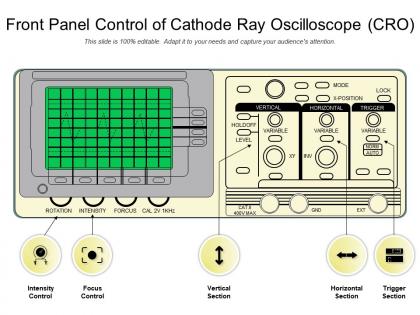
Front panel control of cathode ray oscilloscope cro




Try Before you Buy Download Free Sample Product
 Impress Your
 Audience
 100%
100% Editable
 Save Hours
 of Time


Our Front Panel Control Of Cathode Ray Oscilloscope CRO are explicit and effective. They combine clarity and concise expression.
People who downloaded this PowerPoint presentation also viewed the following :
Front panel control of cathode ray oscilloscope cro with all 2 slides:
Give your audience a fulfilling experience. They will find our Front Panel Control Of Cathode Ray Oscilloscope CRO elevating.
FAQs for Front panel control of cathode
So the vertical stuff adjusts your voltage scale and moves the trace up/down on screen. Horizontal controls are for time - how fast it sweeps and left/right position. Vertical = voltage zoom, horizontal = time zoom basically. You'll mess with the time/div knob constantly, it sets how much time each grid square represents. I always start by getting the signal visible first with vertical position and volts/div, then play with the time base until you can see however many cycles look good across the screen. That time/div knob becomes second nature pretty quick.
So the time base basically controls how fast the electron beam moves across your screen - that changes what each division means time-wise. Faster settings like microseconds will stretch out fewer cycles, which is great for seeing details. Slower ones (milliseconds) squish more cycles together so you get the whole picture. Honestly I'm always messing with this knob! Oh, and pro tip - aim for 2-3 complete cycles across your screen. Start somewhere in the middle then just tweak it until it looks right.
So basically the intensity knob controls how bright your trace shows up - it's adjusting the electron beam current. If you're dealing with weak signals or your room's pretty bright, turn it up so you can actually see the damn thing. Think of it like your phone brightness. Just don't crank it all the way up when you're using slow sweeps, especially on older scopes - you can literally burn the phosphor screen (learned that one the hard way). Start somewhere in the middle and bump it up till you get good visibility.
So the trigger control is what stops that annoying rolling mess you see on the screen. Basically it waits for your signal to hit a specific voltage before starting each trace. That way every sweep begins at the same point in your waveform cycle - boom, stable display. It's honestly one of those things that seems complicated until you mess with it once. Just grab a sine wave and twist the trigger level dial around. You'll totally see it snap into place when you find the sweet spot. Makes all the difference between a usable scope and a headache machine.
Dude, bandwidth limits will totally screw with your high-frequency stuff - cuts off the fast parts and makes everything look rounded and slow. Your square waves end up looking like sine waves, which is super frustrating when you're trying to figure out what's wrong with digital circuits. I learned this the hard way last month actually. Rule of thumb: scope bandwidth should be 3-5x higher than whatever you're measuring. So 10MHz signal needs at least a 30-50MHz scope. Always check your specs first or you'll waste hours chasing problems that don't even exist.
Start with the built-in cal signal - most scopes have that 1kHz square wave at 1V or 2V peak-to-peak. Hook your probe up and tweak the vertical gain until it matches the spec exactly. The timebase needs checking too, so make sure that frequency reads dead-on at 1kHz. Also zero out your DC offset and fix probe compensation if you're not using 1:1. Honestly, I do this every time I power up because weird measurements will drive you crazy otherwise. Takes like two minutes but saves hours of troubleshooting phantom issues later.
So basically, DC coupling shows your whole signal - AC stuff plus any DC offset. AC coupling uses a capacitor to block the DC part, which is clutch when you've got tiny AC signals sitting on huge DC voltages that would wreck your screen. GND just disconnects everything and gives you a flat reference line. Most of the time you'll want DC mode, but honestly AC mode is a lifesaver when you're trying to see small changes without all that DC bias screwing up your scaling. Pretty straightforward once you mess with it.
Oh man, cursors are a lifesaver! They're just movable lines you drop on your scope screen to get exact measurements. Way better than squinting at those tiny grid marks. Drop two cursors anywhere and it automatically calculates the difference - perfect for voltage, timing, frequency, whatever you need. The values pop right up on screen so you don't have to do math like some caveman. Honestly saved me so many headaches in lab. You can measure rise times, pulse widths, all that stuff down to your scope's resolution limits. Just point, click, read the delta.
For everyday stuff, you'll want standard 10:1 and 1:1 passive probes - they handle most measurements without breaking the bank. Active probes work great for high-frequency signals, current probes let you measure current waveforms, and differential probes are clutch when measuring between non-ground points. But honestly? That basic 10:1 probe does like 90% of everything I throw at it. Just double-check your probe matches the scope's input impedance (usually 1MΩ) and has the right connector. I'd say grab a decent 10:1 probe first - it'll cover most troubleshooting you'll run into.
Persistence basically shows trace afterglow for a few seconds after the beam moves - super useful for catching glitches that flash by too quick to see normally. Honestly game-changer for intermittent signals. With longer settings you can overlay multiple waveforms and compare them easily. I always forget how handy it is until I'm troubleshooting some weird digital timing issue, then I'm like "oh right, persistence mode exists." Variable persistence works great for spotty signals - you'll spot timing problems way faster than regular sweep. Definitely try it next time you're hunting down something that only happens occasionally.
So analog scopes are all physical controls - you're literally turning knobs for everything like timebase and voltage. Digital ones mix real knobs with menu screens, which honestly took me forever to get used to. You still get some satisfying physical dials, but stuff like measurements and fancy triggering happens through LCD menus now. The upside? You can actually save your settings instead of losing everything when someone else uses it. There's definitely a learning curve with all the menu navigation, but once you figure it out, digital gives you way more options to play with.
So external triggers let you sync your scope with signals that aren't even plugged into your main channels - pretty cool actually. You can trigger off a clock or logic pulse while measuring totally different stuff on your display channels. Makes debugging digital circuits way easier since you're not stuck only triggering on what you're looking at. I use it all the time when I need to see how different parts of a circuit relate timing-wise. Honestly changed how I approach a lot of measurements once I figured it out.
Dude, get proper high-voltage differential probes - those regular 10:1 ones are useless past a few hundred volts. Your CRO needs solid grounding, and here's something my old professor taught me: keep one hand in your pocket while probing. Sounds weird but it stops current from going through your chest. I've watched people toast expensive gear on car ignition systems because they didn't check their probe's voltage rating first. Oh, and clear your bench of metal crap. Never do this stuff alone either - that's just asking for trouble. Start on lowest sensitivity and bump it up gradually.
Check out the Math menu button first - that's where you'll find basic stuff like addition and subtraction between channels. Most scopes let you mix Ch1 and Ch2 together, which is clutch for differential measurements. FFT is honestly where things get interesting though. It flips your time signals into frequency domain so you can catch components that are totally invisible otherwise. Oh, and make sure your sampling rate's dialed in before you start playing with math functions. I learned that one the hard way - got super confusing results that had me doubting my setup for like an hour.
YT mode plots amplitude over time - that's what you'll use 99% of the time for basic waveform stuff. But XY mode? That's where it gets fun. It plots one input against the other, so you can see phase relationships and those trippy Lissajous patterns. Honestly, XY mode feels like magic when you're comparing two sine waves and get those flower shapes. Stick with YT for your everyday signal analysis. Switch to XY when you need to see how two signals relate to each other directly.
No Reviews